One-stop Solution for Wire and Cable
Email:info@qingzhou-cable.com
WhatsApp/WeChat/Skype/Phone:+8618625503172

WhatsApp/WeChat/Skype/Phone:+8618625503172

 Email:
info@qingzhou-cable.com
Email:
info@qingzhou-cable.com
 Tel:
+8618625503172
Tel:
+8618625503172
 Fax:
+8618625503172
Fax:
+8618625503172
 Skype:
+8618625503172
Skype:
+8618625503172
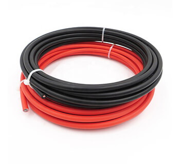
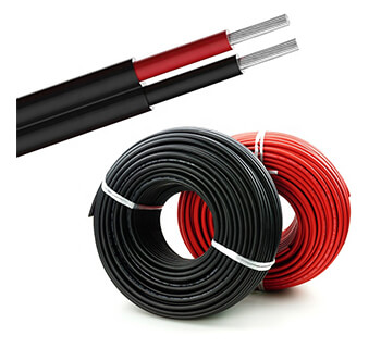
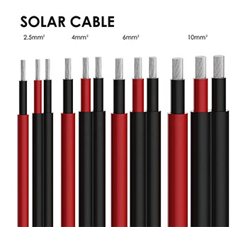
Photovoltaic Cable are designed for connecting photovoltaic system components inside and outside of buildings and equipment with high mechanical requirements and extreme weather conditions.This product type is TUV approved.
Key Features: Photovoltaic PV H1Z2Z2-K Cable
Application: DC Power Cable for the interconnection of photovoltaic systems.
Suitability: For fixed installations, internal and external, including direct burial.
Standards & Voltage Ratings: EN 50618. Flame retardant to IEC/EN 60332-1-2. Low Smoke Zero Halogen to IEC/EN 60754-1/2, IEC/EN 61034-1/2. Water Resistant to AD8. Rated AC: 0.6/1kV and DC: 900/1800V.
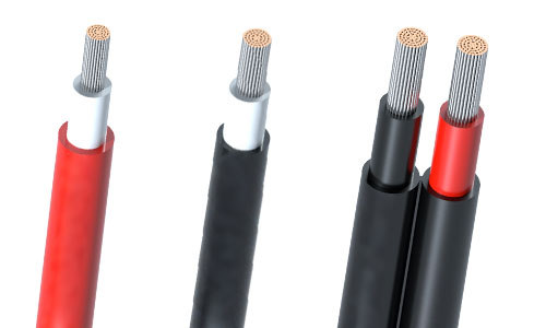
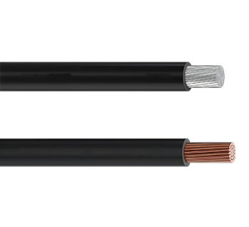
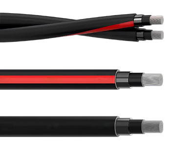
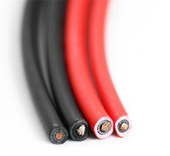
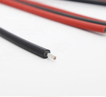
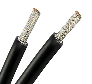
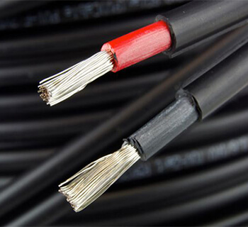
Construction: Class 5 Flexible Tinned Copper conductor, Halogen Free Cross-linked compound insulation, and Halogen Free Cross-linked Flame Retardant compound outer sheath.
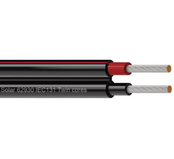
Details: Single core. 'Double-insulation' construction offering increased safety. TUV approved. UV and Ozone resistant. Full technical support provided.
Our photovoltaic (PV) cables are intended for interconnecting power supplies within renewable energy photovoltaic systems such as solar panel arrays in solar energy farms. They are used for installation at Direct Current (DC) side. They are suitable for fixed installations, both internal and external, and within conduits or systems. Their robust sheathing and impact testing means they are suitable for direct burial in ground applications.
They are manufactured in accordance with European Standard EN 50618 and the harmonised designation H1Z2Z2-K. These cables are TUV approved, and this standard supersedes the previous TÜV approved PV1-F cable.
The compounds used in the insulation and outer sheathing are halogen free cross-linked, hence the reference to these cables as "cross-linked solar power cables". The EN50618 standard sheathing has a thicker wall than the PV1-F cable version. The cable sheathing is rated AD8 Water Resistant.
As with the previous TÜV PV1-F cable, the EN50618 PV cable benefits from a double-insulation offering increased safety. The Low Smoke Zero Halogen (LSZH) insulation and sheathing makes them suitable for use in environments where corrosive smoke would present a risk to human life in the event of fire.
With a nominal DC voltage of up to 1.5kV between conductors, and not exceeding 1800V between conductor and earth, these cables are required to be tested at a voltage of 11kV AC 50Hz. They have an operating temperature range of -40oC to +90oC.
Construction
|
Conductor | Stranded tinned copper conductor per DIN VDE 0295 and IEC 60228 Class 5. |
Insulation | Electron beam cross-linked, halogen free and flame retardant compound. |
Sheath | Electron beam cross-linked, LSZH and flame retardant compound, Black. |
| VOLTAGE | AC: 0.6/1kV |
| CONDUCTOR | Class 5 Flexible Stranded Tinned Copper |
| INSULATION | Halogen-Free Cross-Linked Compound |
| OUTER SHEATH | Halogen-Free Cross-Linked, Flame Retardant Compound |
Parameter/Data Sheet
Please click or download below Medium Voltage Power Cable Catalogue to check the parameter.
![]() Photovoltaic_Cable_TUV_EN_50618-Q.pdf
Photovoltaic_Cable_TUV_EN_50618-Q.pdf
Electrical Properties
Rated Voltage U0/U | 1/1 kV AC; 1.5/1.5 kV DC |
Maximum Permitted DC Voltage | 1.8 kV DC (conductor/conductor, non earthed system, circuit not under load) |
Insulation Resistance | 1000 MΩ-km |
Spark Test | 6000 Vac (8400 Vdc) |
Voltage Withstand | 6500 Vac for 5 minElectron |
Thermal Properties
Maximum Voltage | 1.2KV (AC), 1.8KV (DC) |
Ambient Temperature | -40℃ ~ +90℃ |
Maximum Temperature At Conductor | 120℃ (20000h) according to IEC/EN 60216-1 |
Short Circuit Temperature | 200℃/5 sec |
Thermal Endurance Test | According to EN 60216-2 (temperature index +120° C) |
Damp-Heat Resistance | According to EN 50618, Table 2with 85% humidity(test acc. to EN 60068-2-78) |
Mechanical Properties
Minimum Bending Radius | 4×OD (fixed), 5×OD (flexing) |
Dynamic Penetration | According to Acc. to EN 50618, Annex D,Meets requirements of EN 50618. |
Tensile Strength And Elongation Of Insulation And Jacket | 250℃ |
Anticipated Period Of Use | 25 years |
Ovality | ≤15% |
Chemical Properties
Ozone Resistance | According to EN 60811-403(25℃,24h,(250 to 300) × 10-4%) ;Method B: EN 50396(40℃,72h,55%RH, (200 × 10-6%) |
Weathering- UV Resistance (Resistance on sheath) | Tensile strength and elongation at break after 720h (360 Cycles) of exposure to UV lights (acc. to EN 50289-4-17, Method A According to HD 605/A1) |
Ammoniac resistant | |
Very good resistance to oils and chemicals | |
High wear and robust, abrasion resistant | |
EC directives
The cables are conform to the EC directives CE 2006/95/EC (Low voltage directive) and RoHS 2002/95/EC (Restriction of Hazardous Substances).
Fire Performance
Flame retardant according to EN 50265-2-1, IEC 60332-1, VDE 0482-332-1-2, DIN EN 60332-1-2 |
Low smoke emission according to EN 61034-2 (Light Transmittance ≥60%) |
Halogen free according to EN 50525-1, Annex B |
Low corrosivity of gases according to EN 50267-2-2, IEC 60754-2 |
Dimensions and Weight
No. of Cores × Nominal Cross Section | No. of Stranding | Nominal Conductor Diameter | Nominal Insulation Thickness | Nominal Sheath Thickness | Nominal Overall Diamater | Nominal Weight |
No. ×mm^2 | mm | mm | mm | mm | kg/km | |
1×1.5 | 30/0.25 | 1.58 | 0.70 | 0.80 | 5.4 | 40 |
1×2.5 | 50/0.25 | 2.04 | 0.70 | 0.80 | 5.9 | 50 |
1×4.0 | 56/0.30 | 2.59 | 0.70 | 0.80 | 6.6 | 70 |
1×6.0 | 84/0.30 | 3.17 | 0.70 | 0.80 | 7.4 | 80 |
1×10 | 78/0.40 | 4.07 | 0.70 | 0.80 | 8.8 | 130 |
1×16 | 128/0.40 | 5.22 | 0.70 | 0.90 | 10.1 | 200 |
1×25 | 199/0.40 | 6.51 | 0.90 | 1.00 | 12.5 | 290 |
1×35 | 279/0.40 | 7.71 | 0.90 | 1.10 | 14.0 | 400 |
1×50 | 396/0.40 | 9.00 | 1.00 | 1.20 | 16.3 | 550 |
1×70 | 360/0.50 | 10.8 | 1.10 | 1.20 | 18.7 | 750 |
1×95 | 475/0.50 | 12.6 | 1.10 | 1.30 | 20.8 | 970 |
1×120 | 608/0.50 | 14.2 | 1.20 | 1.30 | 22.8 | 1220 |
1×150 | 756/0.50 | 15.8 | 1.40 | 1.40 | 25.5 | 1510 |
1×185 | 925/0.50 | 17.4 | 1.60 | 1.60 | 28.5 | 1850 |
1×240 | 1221/0.50 | 20.4 | 1.70 | 1.70 | 32.1 | 2400 |
Current Carrying Capacity
Cross Section | AWG | Maximum Conductor Resistance at 20℃ | Maximum insulation Resistance at 20℃ | Maximum insulation Resistance at 90℃ | Current Carrying Capacity | ||
Single cable free in air | Single cable on surfaces | 2 loaded cables adjacent on surfaces | |||||
mm^2 | - | Ω | MΩ.km | MΩ.km | A | A | A |
1.5 | 16 | 13.7 | 859 | 0.859 | 30 | 29 | 24 |
2.5 | 14 | 8.21 | 691 | 0.691 | 41 | 39 | 33 |
4 | 12 | 5.09 | 579 | 0.579 | 55 | 52 | 44 |
6 | 10 | 3.39 | 499 | 0.499 | 70 | 67 | 57 |
10 | 8 | 1.95 | 424 | 0.424 | 98 | 93 | 79 |
16 | 6 | 1.24 | 342 | 0.342 | 132 | 125 | 107 |
25 | 4 | 0.795 | 339 | 0.339 | 176 | 167 | 142 |
35 | 2 | 0.565 | 287 | 0.287 | 218 | 207 | 176 |
50 | 1/0 | 0.393 | 268 | 0.268 | 276 | 262 | 221 |
70 | 2/0 | 0.277 | 247 | 0.247 | 347 | 330 | 278 |
95 | 3/0 | 0.210 | 220 | 0.220 | 416 | 395 | 333 |
120 | 4/0 | 0.164 | 211 | 0.211 | 488 | 464 | 390 |
150 | 300 kcmil | 0.132 | 206 | 0.206 | 566 | 538 | 453 |
185 | 350 kcmil | 0.108 | 200 | 0.200 | 644 | 612 | 515 |
240 | 450 kcmil | 0.082 | 198 | 0.198 | 775 | 736 | 620 |
Conversion Factor for Deviating Temperatures
Ambient Temperature ℃ | Conversion Factor |
Up to 60 | 1.00 |
70 | 0.91 |
80 | 0.82 |
90 | 0.71 |
100 | 0.58 |
110 | 0.41 |
Reduction factor for accumulation according to IEC 60364-5-52, Table B.52-17
*Describe Your Buying Requirements in Detail