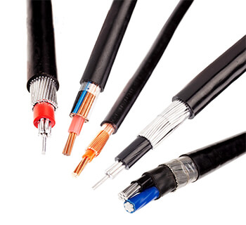
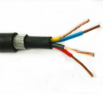
One-stop Solution for Wire and Cable
Email:info@qingzhou-cable.com
WhatsApp/WeChat/Skype/Phone:+8618625503172

WhatsApp/WeChat/Skype/Phone:+8618625503172

 Email:
info@qingzhou-cable.com
Email:
info@qingzhou-cable.com
 Tel:
+8618625503172
Tel:
+8618625503172
 Fax:
+8618625503172
Fax:
+8618625503172
 Skype:
+8618625503172
Skype:
+8618625503172
IEC 60228
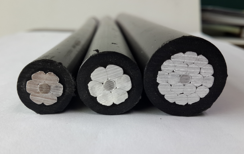
Solid aluminium and solid aluminium alloy conductors (Class1)
Stranded circular non-compacted conductors,Stranded compacted circular conductors and stranded shaped conductors (class 2);Flexible conductors (classes 5 and 6)
Application:
Classification:
The conductors have been divided into four classes, 1, 2, 5 and 6. Those in classes 1 and 2 are intended for use in cables for fixed installations. Classes 5 and 6 are intended for use in flexible cables and cords but may also be used for fixed installations.
Materials
− Class 1: solid conductors.
− Class 2: stranded conductors.
− Class 5: flexible conductors.
− Class 6: flexible conductors which are more flexible than class 5.
Solid aluminium and solid aluminium alloy conductors of sizes 10 mm2 to 35 mm2 shall be of circular cross-section. Larger sizes shall be of circular cross-section for single-core cables and may be of either circular or shaped cross-section for multi-core cables.
Solid copper conductors shall be of circular cross-section. Solid copper conductors having nominal cross-sectional areas of 25 mm2 and above are for particular types of cable, e.g. mineral insulated, and not for general purposes.
Stranded aluminium or aluminium alloy conductors shall have a cross-sectional area not less than 10 mm2. The wires in each conductor shall all have the same nominal diameter.
Table 1 – Class 1 solid conductors for single-core and multicore cables
1 | 2 | 3 | 4 |
Nominal cross-sectional area
mm2 | Maximum resistance of conductor at 20 °C | ||
Circular, annealed copper conductors | Aluminium and aluminium alloy conductors, circular or shaped c Ω/km | ||
Plain
Ω/km |
Metal-Coated
Ω/km | ||
0,5 0,75 1,0 1,5 2,5 4 6 10 16 25 35 50 70 95 120 150 185 240 300 400 500 630 800 1 000 1 200 | 36,0 24,5 18,1 12,1 7,41 4,61 3,08 1,83 1,15 0,727 b 0,524 b 0,387 b 0,268 b 0,193 b 0,153 b 0,124 b 0,101 b 0,0775 b 0,0620 b 0,0465 b - - - - - | 36,7 24,8 18,2 12,2 7,56 4,70 3,11 1,84 1,16 - - - - - - - - - - - - - - - - | - - - - - - - 3,08 a 1,91 a 1,20 a 0,868 a 0,641 0,443 0,320 d 0,253 d 0,206 d 0,164 d 0,125 d 0,100 d 0,0778 0,0605 0,0469 0,0367 0,0291 0,0247 |
a Aluminium conductors 10 mm2 to 35 mm2 circular only; see 5.1.1 c). b See note to 5.1.1 b). c See note to 5.1.2. d For single core cables, four sectoral shaped conductors may be assembled into a single circular conductor. The maximum resistance of the assembled conductor shall be 25 % of that of the individual component conductors. | |||
Table 2 – Class 2 stranded conductors for single-core and multi-core cables
1 | 2 | 3 | 4 | 5 | 6 | 7 | 8 | 9 | 10 |
Nominal cross- sectional area
mm2 | Minimum number of wires in the conductor | Maximum resistance of conductor at 20°C | |||||||
Circular | Circular compacted | Shaped | Annealed copper conductor | Aluminium or aluminium alloy conductorc
Ω/km | |||||
Cu | Al | Cu | Al | Cu | Al | Plain wires
Ω/km | Metal-coated wires Ω/km | ||
0,5 | 7 | - | - | - | - | - | 36,0 | 36,7 | - |
0,75 | 7 | - | - | - | - | - | 24,5 | 24,8 | - |
1,0 | 7 | - | - | - | - | - | 18,1 | 18,2 | - |
1,5 | 7 | - | 6 | - | - | - | 12,1 | 12,2 | - |
2,5 | 7 | - | 6 | - | - | - | 7,41 | 7,56 | - |
4 | 7 | - | 6 | - | - | - | 4,61 | 4,70 | - |
6 | 7 | - | 6 | - | - | - | 3,08 | 3,11 | - |
10 | 7 | 7 | 6 | 6 | - | - | 1,83 | 1,84 | 3,08 |
16 | 7 | 7 | 6 | 6 | - | - | 1,15 | 1,16 | 1,91 |
25 | 7 | 7 | 6 | 6 | 6 | 6 | 0,727 | 0,734 | 1,20 |
35 | 7 | 7 | 6 | 6 | 6 | 6 | 0,524 | 0,529 | 0,868 |
50 | 19 | 19 | 6 | 6 | 6 | 6 | 0,387 | 0,391 | 0,641 |
70 | 19 | 19 | 12 | 12 | 12 | 12 | 0,268 | 0,270 | 0,443 |
95 | 19 | 19 | 15 | 15 | 15 | 15 | 0,193 | 0,195 | 0,320 |
120 | 37 | 37 | 18 | 15 | 18 | 15 | 0,153 | 0,154 | 0,253 |
150 | 37 | 37 | 18 | 15 | 18 | 15 | 0,124 | 0,126 | 0,206 |
185 | 37 | 37 | 30 | 30 | 30 | 30 | 0,0991 | 0,100 | 0,164 |
240 | 37 | 37 | 34 | 30 | 34 | 30 | 0,0754 | 0,0762 | 0,125 |
300 | 61 | 61 | 34 | 30 | 34 | 30 | 0,0601 | 0,0607 | 0,100 |
400 | 61 | 61 | 53 | 53 | 53 | 53 | 0,0470 | 0,0475 | 0,0778 |
500 | 61 | 61 | 53 | 53 | 53 | 53 | 0,0366 | 0,0369 | 0,0605 |
630 | 91 | 91 | 53 | 53 | 53 | 53 | 0,0283 | 0,0286 | 0,0469 |
800 | 91 | 91 | 53 | 53 | - | - | 0,0221 | 0,0224 | 0,0367 |
1 000 | 91 | 91 | 53 | 53 | - | - | 0,0176 | 0,0177 | 0,0291 |
1 200 | b | 0,0151 | 0,0151 | 0,0247 | |||||
1 400 a | b | 0,0129 | 0,0129 | 0,0212 | |||||
1 600 | b | 0,0113 | 0,0113 | 0,0186 | |||||
1 800 a | b | 0,0101 | 0,0101 | 0,0165 | |||||
2 000 | b | 0,0090 | 0,0090 | 0,0149 | |||||
2 500 | b | 0,0072 | 0,0072 | 0,0127 | |||||
a These sizes are non-preferred. Other non-preferred sizes are recognized for some specialized applications but are not within the scope of this standard. b The minimum number of wires for these sizes is not specified. These sizes may be constructed from 4, 5 or 6 equal segments (Milliken). c For stranded aluminium alloy conductors having the same nominal cross-sectional area as an aluminium conductor the resistance value should be agreed between the manufacturer and the purchaser. | |||||||||
1 | 2 | 3 | 4 |
Nominal cross-sectional area mm2 | Maximum diameter of wires in conductor mm | Maximum resistance of conductor at 20 °C | |
Plain wires
Ω/km | Metal-coated wires
Ω/km | ||
0,5 | 0,21 | 39,0 | 40,1 |
0,75 | 0,21 | 26,0 | 26,7 |
1,0 | 0,21 | 19,5 | 20,0 |
1,5 | 0,26 | 13,3 | 13,7 |
2,5 | 0,26 | 7,98 | 8,21 |
4 | 0,31 | 4,95 | 5,09 |
6 | 0,31 | 3,30 | 3,39 |
10 | 0,41 | 1,91 | 1,95 |
16 | 0,41 | 1,21 | 1,24 |
25 | 0,41 | 0,780 | 0,795 |
35 | 0,41 | 0,554 | 0,565 |
50 | 0,41 | 0,386 | 0,393 |
70 | 0,51 | 0,272 | 0,277 |
95 | 0,51 | 0,206 | 0,210 |
120 | 0,51 | 0,161 | 0,164 |
150 | 0,51 | 0,129 | 0,132 |
185 | 0,51 | 0,106 | 0,108 |
240 | 0,51 | 0,0801 | 0,0817 |
300 | 0,51 | 0,0641 | 0,0654 |
400 | 0,51 | 0,0486 | 0,0495 |
500 | 0,61 | 0,0384 | 0,0391 |
630 | 0,61 | 0,0287 | 0,0292 |
Table 4 – Class 6 flexible copper conductors for single-core and multi-core cables
1 | 2 | 3 | 4 |
Nominal cross-sectional area
mm2 | Maximum diameter of wires in conductor mm | Maximum resistance of conductor at 20 °C | |
Plain wires Ω/km | Metal-coated wires Ω/km | ||
0,5 | 0,16 | 39,0 | 40,1 |
0,75 | 0,16 | 26,0 | 26,7 |
1,0 | 0,16 | 19,5 | 20,0 |
1,5 | 0,16 | 13,3 | 13,7 |
2,5 | 0,16 | 7,98 | 8,21 |
4 | 0,16 | 4,95 | 5,09 |
6 | 0,21 | 3,30 | 3,39 |
10 | 0,21 | 1,91 | 1,95 |
16 | 0,21 | 1,21 | 1,24 |
25 | 0,21 | 0,780 | 0,795 |
35 | 0,21 | 0,554 | 0,565 |
50 | 0,31 | 0,386 | 0,393 |
70 | 0,31 | 0,272 | 0,277 |
95 | 0,31 | 0,206 | 0,210 |
120 | 0,31 | 0,161 | 0,164 |
150 | 0,31 | 0,129 | 0,132 |
185 | 0,41 | 0,106 | 0,108 |
240 | 0,41 | 0,0801 | 0,0817 |
300 | 0,41 | 0,0641 | 0,0654 |
1 | 2 | 1 | 2 |
Temperature of conductor at time of measurement t °C | Correction factor, kt All conductors | Temperature of conductor at time of measurement t °C | Correction factor, kt All conductors |
0 | 1,087 | 21 | 0,996 |
1 | 1,082 | 22 | 0,992 |
2 | 1,078 | 23 | 0,988 |
3 | 1,073 | 24 | 0,984 |
4 | 1,068 | 25 | 0,980 |
5 | 1,064 | 26 | 0,977 |
6 | 1,059 | 27 | 0,973 |
7 | 1,055 | 28 | 0,969 |
8 | 1,050 | 29 | 0,965 |
9 | 1,046 | 30 | 0,962 |
10 | 1,042 | 31 | 0,958 |
11 | 1,037 | 32 | 0,954 |
12 | 1,033 | 33 | 0,951 |
13 | 1,029 | 34 | 0,947 |
14 | 1,025 | 35 | 0,943 |
15 | 1,020 | 36 | 0,940 |
16 | 1,016 | 37 | 0,936 |
17 | 1,012 | 38 | 0,933 |
18 | 1,008 | 39 | 0,929 |
19 | 1,004 | 40 | 0,926 |
20 | 1,000 | ||
NOTE The values of correction factors kt are based on a resistance-temperature coefficient of 0,004 per K at 20 °C. The values of temperature correction factors specified in column 2 are approximate but give practical values well within the accuracy that can normally be achieved in the measurements of conductor temperature and length of cables or flexible cords. For more accurate values for the temperature correction factors for copper and aluminium, reference should be made to Annex B. However, these should not be treated as a requirement for testing in compliance with this standard in the assessment of resistances. | |||
1 | 2 | 3 | 4 |
Cross sectional area mm2 | Conductors in cables for fixed installations |
Flexible conductors (Classes 5 and 6) mm | |
Solid (Class 1) mm | Stranded (Class 2) mm | ||
0,5 | 0,9 | 1,1 | 1,1 |
0,75 | 1,0 | 1,2 | 1,3 |
1,0 | 1,2 | 1,4 | 1,5 |
1,5 | 1,5 | 1,7 | 1,8 |
2,5 | 1,9 | 2,2 | 2,4 |
4 | 2,4 | 2,7 | 3,0 |
6 | 2,9 | 3,3 | 3,9 |
10 | 3,7 | 4,2 | 5,1 |
16 | 4,6 | 5,3 | 6,3 |
25 a | 5,7 | 6,6 | 7,8 |
35 a | 6,7 | 7,9 | 9,2 |
50 a | 7,8 | 9,1 | 11,0 |
70 a | 9,4 | 11,0 | 13,1 |
95 a | 11,0 | 12,9 | 15,1 |
120 a | 12,4 | 14,5 | 17,0 |
150 a | 13,8 | 16,2 | 19,0 |
185 | 15,4 | 18,0 | 21,0 |
240 | 17,6 | 20,6 | 24,0 |
300 | 19,8 | 23,1 | 27,0 |
400 | 22,2 | 26,1 | 31,0 |
500 | - | 29,2 | 35,0 |
630 | - | 33,2 | 39,0 |
800 | - | 37,6 | - |
1 000 | - | 42,2 | - |
NOTE The values given for flexible conductors are intended to allow for both class 5 and class 6 conductors. | |||
a See 5.1.1 b). | |||
Table C.2 – Minimum and maximum diameters of stranded compacted circular copper, aluminium and aluminium alloy conductors
1 | 2 | 3 |
Cross-sectional area mm2 | Stranded compacted circular conductors ( Class 2 ) | |
Minimum diameter mm | Maximum diameter mm | |
10 16 25 35 50 70 95 120 150 185 240 300 400 500 630 | 3,6 4,6 5,6 6,6 7,7 9,3 11,0 12,3 13,7 15,3 17,6 19,7 22,3 25,3 28,7 | 4,0 5,2 6,5 7,5 8,6 10,2 12,0 13,5 15,0 16,8 19,2 21,6 24,6 27,6 32,5 |
NOTE 1 The dimensional limits of aluminium conductors with cross-sectional areas above 630 mm2 are not given as the compaction technology is not generally established. NOTE 2 No values are given for compacted copper conductors in the size range 1,5 mm2 to 6 mm2. | ||
1 | 2 | 3 |
Cross-sectional area
mm2 | Solid conductors (class 1) | |
Minimum mm | Maximum mm | |
10 | 3,4 | 3,7 |
16 | 4,1 | 4,6 |
25 | 5,2 | 5,7 |
35 | 6,1 | 6,7 |
50 | 7,2 | 7,8 |
70 | 8,7 | 9,4 |
95 | 10,3 | 11,0 |
120 | 11,6 | 12,4 |
150 | 12,9 | 13,8 |
185 | 14,5 | 15,4 |
240 | 16,7 | 17,6 |
300 | 18,8 | 19,8 |
400 | 21,2 | 22,2 |
500 | 24,0 | 25,1 |
630 | 27,3 | 28,4 |
800 | 30,9 | 32,1 |
1 000 | 34,8 | 36,0 |
1 200 | 37,8 | 39,0 |
AWG | kcmil | ||||||
Conductor size | Nominal cross- sectional area mm2 |
Conductor size | Nominal cross- sectional area mm2 |
Conductor size | Nominal cross- sectional area mm2 |
Conductor size | Nominal cross- sectional area mm2 |
- | - | - | - | 250 | 127 | 750 | 380 |
- | - | - | - | 300 | 152 | 800 | 405 |
20 | 0,519 | 4 | 21,2 | 350 | 177 | 900 | 456 |
18 | 0,823 | 3 | 26,7 | 400 | 203 | 1000 | 507 |
16 | 1,31 | 2 | 33,6 | 450 | 228 | 1200 | 608 |
14 | 2,08 | 1 | 42,4 | 500 | 253 | 1250 | 633 |
12 | 3,31 | 1/0 | 53,5 | 550 | 279 | 1500 | 760 |
10 | 5,26 | 2/0 | 67,4 | 600 | 304 | 1750 | 887 |
8 | 8,37 | 3/0 | 85,0 | 650 | 329 | 2000 | 1010 |
6 | 13,3 | 4/0 | 107 | 700 | 355 | - | - |
*Describe Your Buying Requirements in Detail